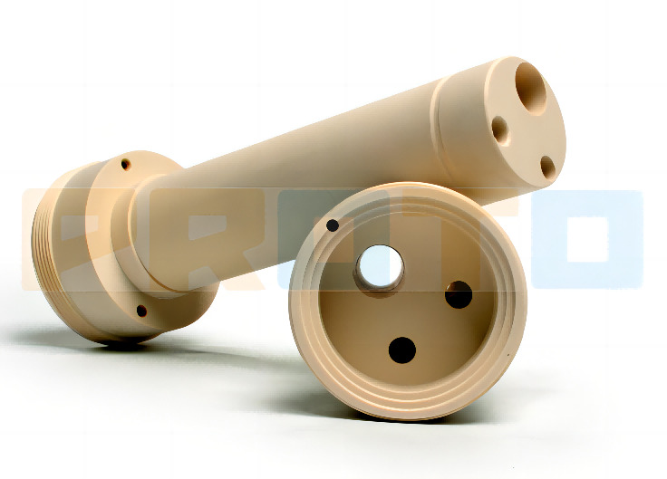
Carbon fiber-reinforced PEEK material effectively improves the wear resistance and mechanical properties of the material after adding carbon fiber. It is a special engineering plastic with excellent performance. Among them, the high wear resistance and outstanding mechanical properties of PEEK5600CF30 material make it widely used in airtight sealing and support positioning parts.
Major problems have also been encountered when turning PEEK5600CF30 materials, such as rapid tool wear and low processing efficiency. When processing high-precision dimensions, the tool compensation value changes greatly, and the processing accuracy is not easy to guarantee. PCD (polycrystalline diamond) tool material has the advantages of tight particle combination, not easy to break and high wear resistance. As a turning tool, the front and rear angles can reach a large value and the cutting force is small, so it is suitable for processing non-metallic materials.
There are currently three major problems facing the processing of PEEK special engineering plastics: first, the use of carbide tools for processing, the tool life is extremely poor; second, the dimensional accuracy and surface roughness of the parts cannot be effectively guaranteed during the processing, and the quality stability is poor; third, turning The processing efficiency is low and the cutting parameters need to be optimized.
Solution
PCD cutting tools
A general PCD tool consists of three parts: metal tool, PCD patch and adhesive layer. Figure 3 is a schematic diagram of a typical PCD blade structure. The cemented carbide metal matrix and the PCD patch are connected by an adhesive layer.
The quality of PCD tools is mainly determined by the grinding quality of PCD patches and the material quality of PCD patches. At present, major domestic PCD tool manufacturers have been able to achieve localization and precision processing of PCD materials. Therefore, the price of domestic PCD cutting tools has dropped from being unattainable in the 1990s to basically the same as high-quality carbide. However, compared with imported PCD tools, domestic PCD tools still have some shortcomings, such as unstable quality and short service life. Some domestic PCD cutting tools use imported materials. Due to domestic processing levels, their edge processing technology still lags behind foreign countries. According to the size of the diamond particles that make up the material, commonly used PCD materials are divided into 20, 30 and 30M grades. The larger the particle size, the larger the material grade. Similar to the particle size of cemented carbide, larger particle sizes have better wear resistance and are suitable for processing harder materials.
Tool selection
Taking the processing of the ejection hook anti-wear ring of a typical part made of PEEK5600CF30 as the test object, carbide tools and PCD tools were used for processing respectively. The difference in wear and wear value changes between the two were observed, and the processing parameters of the two were compared.
During the machining process of cemented carbide inserts, crater wear, flank wear and groove wear on the rake face are prone to occur. In the initial stage of tool wear, the cutting edge is prone to cracking due to the extrusion of carbon fiber; the rake surface coating is rapidly damaged under the friction of the carbon fiber material, and the blade matrix wears rapidly, causing the edge strength to further reduce and the cutting edge damage to intensify; in severe In the wear stage, the flank surface of the tool is seriously worn, and the arc shape of the tool tip is damaged, resulting in a decrease in the machining accuracy of the parts, serious flanging and burrs, and the surface quality cannot be guaranteed.
The blade tip arc radius measured using OLYMPUS high-power electron microscope is 0.34mm, and the blade tip radius of the unused blade is 0.4mm. The difference shows that the deviation of the theoretical tool tip position is -0.06mm. When processing according to the tool tip position measured when processing the first part, it means that the part processing contour error is +0.06mm. Comparison of wall thickness tolerances of antifriction ring parts
mm, this tolerance is enough to cause the part to be scrapped.
After using PCD polycrystalline diamond cutting tools, the tool wear has been effectively improved. Under the same processing time and cutting conditions, only the rake face of the blade has a low degree of wear, the cutting edge is basically intact, and the arc shape of the tool tip maintains high accuracy. The machining accuracy of parts has been greatly improved.
The tool tip arc radius value measured using OLYMPUS high-power electron microscope is 0.385mm, and the tool tip radius of the unused blade is 0.4mm. The difference shows that the deviation of the theoretical tool tip position is -0.015mm. When processing according to the tool tip position measured when processing the first part, it means that the part processing contour error is +0.015mm. Comparison of wall thickness tolerances of antifriction ring parts
mm, the part is still qualified at this time.
Through this test, it can be concluded that carbide inserts are not suitable for turning PEEK5600CF30 materials, and PCD tools are suitable for turning PEEK5600CF30 materials. The use of grade 20 PCD tools can meet the needs.
Processing dimensional accuracy error analysis
(1) The influence of tool cutting force on the processing of anti-friction rings. During the processing of parts, if the CNC program is compiled according to the normal size of the anti-friction ring parts, it is found that the shape of the inner hole and the outer circle after processing have a taper: on the length of 10 to 12 mm, The variation of the inner hole of the part is 0.04~0.05mm, and the variation of the outer circle is 0.01~0.03mm.
The reason is analyzed that the mouth part of the part has low rigidity, and the tool gives way during the cutting process. After processing and debugging, the taper of the parts after processing is compensated in the CNC program to better ensure the processing accuracy. After trial machining of the parts, there is a direct relationship between the cutting amount of the inner hole and the axial length of the parts. The axial size increases and the deformation of the orifice increases. After compensating the taper during the programming process, the machining accuracy of the parts can be effectively improved.
(2) The impact of tool wear on the dimensional accuracy and surface quality of parts. Taking the processing of anti-friction ring parts as an example, the situation verified on site is as follows: after processing 400 pieces, due to severe tool wear, if it continues to be used, it is recommended to process 50 pieces every time. Adjust the tool compensation value and taper once, and adjust the diameter value by 0.02mm each time. The processing conditions are: use CTX310 CNC machine tool to process PEEK5600CF30 bar stock, and the tool is a domestic PCD inner hole boring tool. Processing parameters: spindle speed 1800r/min, feed rate 0.06mm/r, finishing machining allowance 0.05mm, it is not recommended to continue using it after 700 to 800 pieces, and the tool must be changed. The reason for this operation is that the cutting force increases due to tool wear, which in turn affects the dimensional accuracy and surface quality of the part. The tool offset value and the CNC program must be adjusted in time to ensure the part processing qualification rate.
Cutting parameters
Recommended PCD tool brands and corresponding cutting parameters. Conditions for the use of this parameter: The processing machine tool is a CTX310 CNC lathe, the wall thickness of the part is ≥1mm, and the processing outer circle diameter is 30~50mm. In addition, please note that the manufacturer of the PCD blade used above is SECO (Seco), and the tool parameters of other brands can be fine-tuned on this basis.
After research and application on the turning performance of PEEK engineering plastics, the turning efficiency and quality of PEEK5600CF30 material have been effectively improved.
PROTO MFG provides a wide range of manufacturing capabilities and other value-added services for all of your prototyping and production needs. Visit our website to learn more or to request a free, no-obligation quote.