Technical Drawing for CNC Machining
Technical drawings are widely used in CNC machining, sheet metal fabrication, and other manufacturing to facilitate the communication of technical requirements between designers and engineers and manufacturers.
To request a quote for a custom CNC part at PROTO MFG, a 3D CAD file is required.
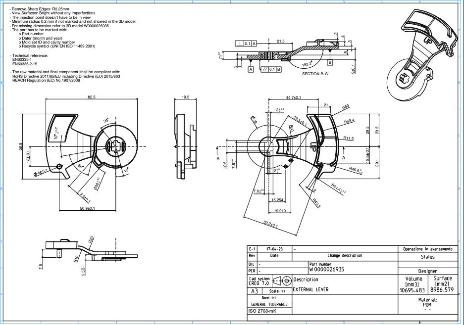
The picture above is a full size technical drawing
Why are technical drawings still important for sourcing and producing parts?
Because technical drawings include some information that cannot be represented in 3D drawings, as follows:
Internal or external threads
Features with out-of-standard tolerances
Individual surfaces with specific finishing requirements
Technical drawings usually consist of the following key components:
Title bar
Isometric/graphical view of the part
Main orthogonal view of the part
Section view or detail view
Manufacturer’s notes
Header bar

Prepare technical drawings in 7 steps
Step 1
Define the most important views and place the relevant orthogonal ones in the center of the drawing, leaving enough space between them to add dimensions.
Step 2
If the part has internal features or complex and difficult-to-dimension areas, consider adding section views or partial views.
Step 3
Add construction lines to all views. Construction lines include centerlines, center marks, and center mark patterns
Step 4
Add dimensions to your CNC machined drawing, starting with the most important ones
Step 5
Specify the location, size and length of all threads.
Step 6
Add tolerances for features that require greater precision than standard tolerances. Refer to ISO 2768 for unspecified tolerances, -m or -f for metals, -m or -c for plastics
Step 7
Fill in the title field and make sure that all relevant information and requirements beyond the standard practice are mentioned in the additional notes